
Home Screen
Here in the Home Screen we can set a picture of our simulator or a picture to make our setup look personal to our tastes.
- Create an image with a size of 600 x 400 in any picture editor. Easiest to do complete it is the Ms Paint, but any drawing application will work just make sure the overall size of the picture is set to 600 x 400.
- Click on the Home button.
- Double Click anywhere in the Home screen then another dialog box should appear.
- Select the picture that you have previously resized to 600 x 400.
- Click Open.
Now your Home Screen should have your picture now showing and will stay this way until you either change this or reset it with:
- Press Tools .
- Press Clear Your Home Pic.
Which will then clear the picture.
Axis Assignments
The axis used by the Game Engine are important to setup correctly as this will decide how your simulator will act to the input coming from the Game Manager.
You can gain access to these by pressing the button marked Axis Assignments located on the top line.
Looking at this page you will notice on the left hand side a list of Axis 1 through to 6; these are the Axis that you may setup to be used by the Interfaces that you will select in Interface settings. They represent the actuators/motors within you simulator as you may guess for a 2 DOF unit you will setup two axes and so on to a 6 DOF unit where you will setup all six axis.
In the center box is a list of DOF which allows you set the forces you wish to act on each axis and can be a collection of up to six allowing for a very complicated axis profile to be easily written. Along with just selecting the forces to use you can apply filters and the % of the total axis movement to be used by each force.
For now we will setup the default axis as this is the most important one to setup first before moving on and installing any game plugin.
Setting up your Default Axis
It is recommended that we first setup our Axis, to test the simulator before testing any game output. So when we actually test a game we only have to fine tune the result.
- Open SimTools Game Engine
- Press Axis Assignments
Now we can build an axis table that looks like this below. The default axis settings are used for any new game plugin that is installed later.
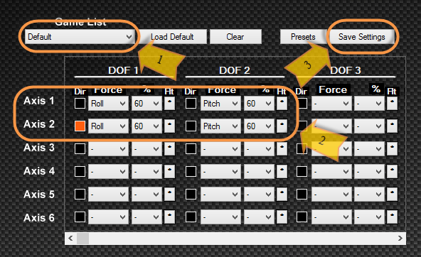
From this you can see that both axis pitches and move in the same direction to create a pitch down and up movement, and for roll they move in an opposite direction to create a roll movement.
Method for setting the default axis settings:
- Click on the Game List box and Select “Default”
- To check what is set for the Axis – Roll and Pitch, noting that roll has one axis is inverted.
- Click “Save Settings” to save the changes to the Sim Engine.
Now we have just set our Default (Base) axis for all new games that are added to the Game Manager but remember we can always come back and change these values for a specific game.
Now what we have actually set in the above Default Axis profiles is for our sim to use 60% of the actuators movement to Roll (Tilt left to right) and to use 60% of the actuator travel to Pitch(tilt forward and backward) and both Roll and Pitch act on both Axis(motors). Please not if only one Axis(motor) controls the Pitch and one controls the Roll you will need to change the Default Axis to represent this.
Due noted that we haven’t included any Surge (longitudinal) and Sway (lateral) or Heave (vertical) to our default axis settings this can be done as well by adding it to the default profile to create a true motion cue.
This also can easily be set by using the supplied presets or from a preset that someone has sent you. This can be handy when copying some else’s design and wish to use the same setting as they have. We will explain below how to select a preset and how to save your own if you wish to send it to someone to try and test.
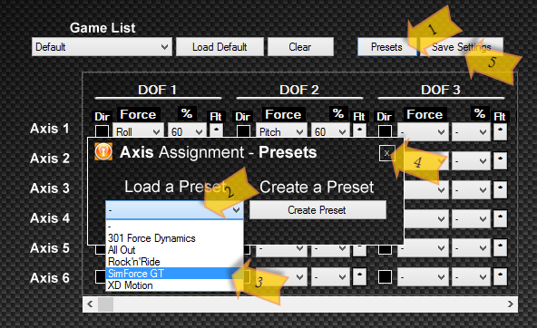
To use a supplied preset:
- Press the button – Presets.
- Press the drop box under Load a Preset.
- Select a preset for example SimForceGT.
- Close this window with the X.
- Press Save Settings to save these values to the Default.
Now we have saved the above settings from the SimForceGT profile to our default axis profile. To be a perfect world we would have a list of all types of profile preset to use but to be fair we are able to create our own and save this so that we are able to send them to each other to make our journey through SimTools a pleasant one.
Filters
You will also notice there is a button under each DOF – Flt which is used to create a filter for each force within the Axis Assignments and can be handy when you refine your axis assignments to improve the feel to your personal requirements.
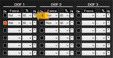
By pressing this button another window will pop up like this below:
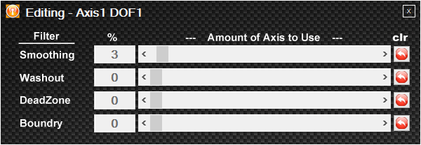
Smoothing – Will smooth the value, if a value seems jerky or not flowing this can be increased to add a smoothing effect by creating a mean value of the values coming in.
Washout – Is handy when we require a value to wash back to 0. i.e. like for a yaw axis that doesn’t actually turn a full 360 degrees. So to give the feeling to the rider that he/she is still actually turning.
Deadzone – Is for setting a deadzone in the middle of the movements i.e. around the 0, so if our Min Max in the tuning center is set to Max 10 Min 10 and we don’t want to feel 3-0-3 we can set a percent to represent this and take these values away from the equation, resulting in a deadzone on the middle of our axis movements.
Boundary – Is to make sure the single DOF does not use more than X amount of the available axis. In turn letting you have a very sensitive axis and will make sure it doesn’t take over the whole axis.
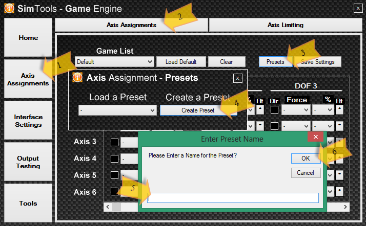
Create a new Preset Axis Assignment
This simple process allows you to save your Axis Assignment settings to allow it to be sent to another user to easily select and install to their SimTools.
After setting all the axis assignment settings correctly:
- Press Axis Assignments on the right hand side button bar.
- Press Axis Assignments on the top button bar just to make sure you are in the right place.
- Press Presets. You will notice a new window pop up.
- Press Create Preset.
- Now type in a recognizable name for your axis assignment preset.
- Press OK to save it.
[gard]
You will notice by pressing Presets and then Load a Preset in the following window, the name of the preset we have saved before will appear in the list. Ok now we need to know where we can retrieve this preset in order to be able to post this onto the website for others or in turn be able to email this to a fellow builder who has asked you for it.
Ok to recover our previous preset in order for us to send it to somewhere please take these following steps:
- Press Tools in the right hand button bar.
- Press Axis Presets in the Preset Management group box.
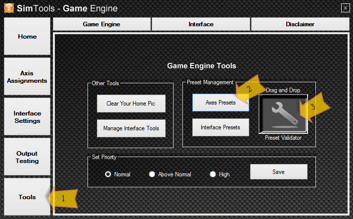
A file manager window will open and you are free to copy the preset to either a post on the web site or an email attachment. Once the person who asked for this or someone who has downloaded this then can apply this to their version of SimTools with these steps:
3. Simply drag and drop the file in question to the Preset Validator.
SimTools will validate it to be sure it is not corrupt and install it to the correct location and now can be selected by the user to use or just to check if they got theirs right.
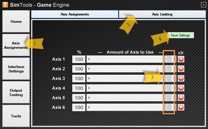
Axis Limiting
Here we can simply set some safety limits in our axis, mainly used for SCN5/6 output as you don’t want the internals smashing against the outer shell which will result in early failure of the very expensive drivers and you may not be able to get a replacement on warranty.
- Press Axis Assignments in the right hand button bar.
- Press Axis Limiting in the top button bar.
- Now change the % of the axis to use by moving the slider for the axis that you wish to limit
- Once happy press Save Settings.
Now this will limit the maximum distance the axis will travel if set right will never reach their internal end stop and damage them and this can be revisited and changed if required.
Interface Settings
The first time clicking on this button might not look like you’re in the right place. Here we can setup our Interfaces, i.e. Motor controller, SCN Controllers and Microcontrollers even set our Interfaces that are connect to the Game Engine PC via the network.
Allowing us to set them all up in one place.
In the top button bar you will notice we can setup six interfaces for the Game Engine to control therefore we can control six interfaces for a 6DOF simulator.
There is also presets already setup and ready for you to just select and go, can save some time and this makes it easier for you if you have one of these supported interfaces. Alongside this too is where you select the type of Output, being Net – An interface that needs to be connected via a IP Address, SCN – for using the SCN5/6 from Mirai Inter-tech and last of all Ser – Serial connected device.
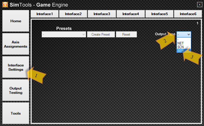
Setting up a Network Interface
Once you have selected Net from the Output Type box you will be given a screen that looks like this:
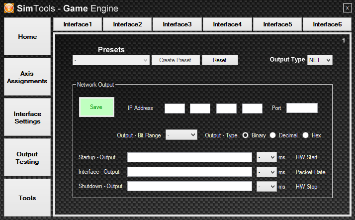
To explain all the areas:
- IP Address – Is the IP address this particular interface is located on.
- Port – Port that the interfaces uses.
- Output – Bit Range – as it states is the range of values SimTools will send.
- Output – Type – Is the format for the value needed by the Interface.
- Startup – Output – If your Interface needs a specific set of commands to set it up. Plus on the end of this you can set a pause for the Interface to do its start up in time before any other command is sent to it – HW Start. IE the time it takes to centre or calibrate itself.
- Interfaces – Output – Will be the format that SimTools will send Axis movements to the selected interface, and an axis is represented as <Axis1> and so on. Again on the end of this there is another setting for setting the time needed for the interface to cycle through the command before it receives another Command – Packet Rate.
- ShutDown – Output – If your interface needs specific commands to shutdown enter them here, as well again we have another setting on the end to allow the interface time to successfully shut down – HW Stop.
Once you are happy with the interface please press Save to save the setting to the Game Engine. On another note it can be handy to Create a Preset with this existing settings in order to send this to another user who has the same device but not the knowledge on how it needs to be setup.
If more than one Net Interface is used you can then select from the top button bar the next Interface and continue to set it up like above.
Setting up a SCN Interface
Once you have selected SCN from the Output Type box you will be given a screen that looks like this:
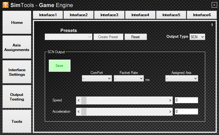
To explain all the area:
- ComPort – Is the Com port the device is connected on.
- Packet Rate – Is the speed needed for it to receive the commands at.
- Assigned Axis – The axis that you wish for this actuator to use.
- Speed – To set the maximum speed you wish to use for this actuator.
- Acceleration – To set the maximum acceleration for the actuator in question.
Again please press Save in order to save these setting to the game engine, and if another one need to be setup, simply click the next Interface in the top button bar and continue to setup like listed above.
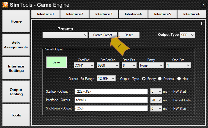
Setting a Serial Interface.
Once you have selected Ser from the Output Type box you will be given a screen that looks like this:
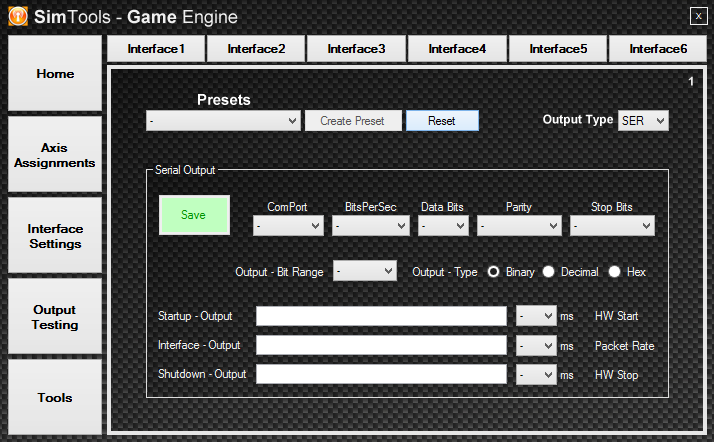
To explain all the areas:
- ComPort – Is the Com port the device is connected on.
- BitsPerSec – Is the Baud Rate at which the interface needs to communicate at.
- Databits – as it states is the data bits that are needed by this interface.
- Parity – as it states is the parity that is needed by this interface.
- Stop Bits – as it states is the Stop Bits that is needed by this interface.
- Output – Bit Range – as it states is the range of values SimTools will send.
- Output – Type – Is the format for the value needed by the interface.
- Startup – Output – If your Interface needs a specific set of commands to set it up. Plus on the end of this you can set a pause for the Interface to do its start up in time before any other command is sent to it – HW Start. IE the time it takes to centre or calibrate itself.
- Interfaces – Output – Will be the format that SimTools will send Axis movements to the selected interface, and an axis is represented as <Axis1> and so on. Again on the end of this there is another setting for setting the time needed for the interface to cycle through the command before it receives another Command – Packet Rate.
- ShutDown – Output – If your interface needs specific commands to shutdown enter them here, as well again we have another setting on the end to allow the interface time to successfully shut down – HW Stop.
Again please press Save in order to save these setting to the game engine, and if another one is needed to be setup, simply click the next Interface in the top button bar and continue to setup like listed above.
Example of Setting a Jrk in as a Serial Interface.
For an example we will step you through an example of a preset supplied with SimTools, others may be added in the future when they show they will be used often enough to include, Developers of custom interfaces can provide a setting file in their post on the site to make this easier for new people to use their custom interface too.
Ok now to setup a Jrk as follows:
- Select the Interface Settings on the right hand button bar.
- Select the Interface Number you wish to set from the top button bar.
- Now select the Ser from the Output Type Drop Box
- Now select Jrk 12bit from the Presets Drop Box.
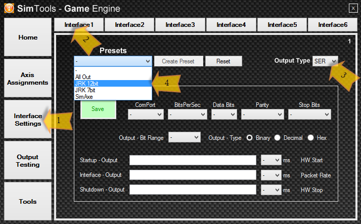
You will notice it will fill in the fields below as needed but is not totally complete. You still need to change a couple of things. As noted below:
- Set the Comport to the command port that the Jrk is using
- Set the BitsPerSec to the baud rate that the Jrk is set to, if you have not changed this in the Device Manager in Windowstm its 9600 by default.
- Set the Packet Rate in the Interface Output to the same as the PID Period in the Jrk Utility , an important one or SimTools will send extra commands when the Jrk is still actually calculating the PID to move the motor to the desired location, may cause lag in movement if set wrong.
- In Interface Output set the <Axis> to the axis you wish this Jrk to use from the Axis Assignments.
- Click Save to save these setting to the Game Engine.
Once happy with all your settings click Save to save the settings to the Game Engine. You can do the same as above to set another Interface if more than one Jrk is needed noting that you need to select the next interface and not overwrite the one you have just done.
Saving an Interface Preset to send to someone to use.
This simple process allows you to save your interface settings to allow it to be either sent to another user or to be posted on the web site so they can easily select and install to their SimTools.
After setting all the interface’s setting correctly:
- Select Create Preset.
Another window will appear and then:
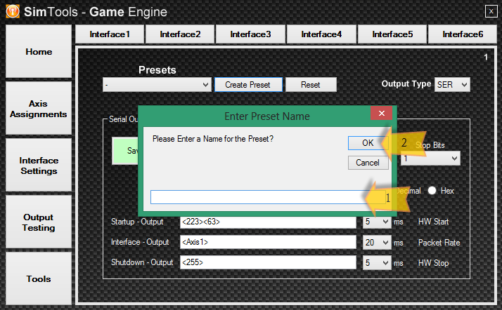
- Type in a name for the preset.
- Click OK to save.
You will notice the new saved preset will now appear in the Presets drop down box.
Ok now to retrieve this preset and send it to someone that may need it:
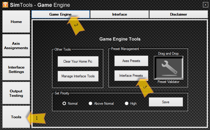
- Press Tools on the right button box area.
- Press Game Engine on the top button box area.
- Press Interface Presets from the Preset Management area.
Now a file manager window will appear and the preset that you have saved will appear here, this then will allow you to copy this or attach it to an email to send to someone who may need this.
They in turn just need to drag and drop this preset to the same area as where you opened the directory and place it in the Preset Validator, from there Sim Tool will take over check that the format is correct and then moves it to the right place that is needed. Then the user can continue back to the Interface Settings and now can select the preset that you have sent or posted on the website.
Output Testing
Now this is an important phase of setting up, you will need to test the output to the interfaces so that you know that the directions do as they were applied and match what is needed by the Game Plugins in order to move your sim in the correct way.
- Press Output Settings in the left hand button box.
- Press Turn On.
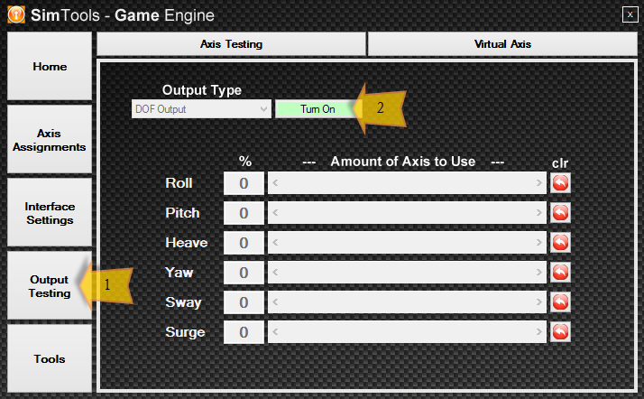
If your settings in the Interface Settings are set correctly your interfaces should show they are receiving data and most will come to their center positions and await the next command. Now there is actually two options for testing the output and are explained below:
Testing Output via DOF
This is the default option already selected and as it actually looks this allows you to simulate the roll, pitch, etc. as if it was receiving these values from the game plugin, and please note it uses the default axis settings from the Axis Assignments and if you have not set the Roll there the roll here will not affect the sim at all. Now by moving the sliders you can test the directions and make sure that they match the direction set in the SimTools Co – ordinate System. Please note that the clr button resets the value to 0 which should be your center.
The second option can be found by selecting it from the Output Type drop down box.
Testing Output via Axis
This will allow you to test each axis individually and is handy to make sure each axis is moving to its correct limits and can re center itself properly and repeats this.
Once you are happy that it actually moves in all the correct ways simply Turn Off to exit.
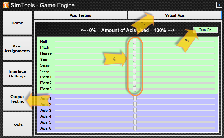
Virtual Axis
The virtual axis can be a very handy tool to check that the data coming in from the plugin is actually moving the track bars in the right manner to what is set out in our Co-ordinate system.
If you find that they do not comply please post a polite comment to the developer listed with in the plugin so that they may change to this, if this co-ordinate system is not followed it will make it hard for people to make sure their Axis Assignment’s for each game are correct.
A note to existing and new plugin developers, please make sure your plugin match the Co-ordinate system that is in place, makes it so much easier for everybody else.
You need to use with the game running and is better with the game running in a window on a single screen system:
- Press Output Testing from the right button bar.
- Press Virtual Axis on the top button bar.
- Press Turn On in the resulting window.
- Now drive or fly in the game keeping one eye on track bars to make sure they are moving in their correct directions.
Tools
Provided with the Game Engine is a set of simple tools that make doing certain tasks a lot easier and contains three sections. These sections can be each selected from the top button bar and are listed as the following:
- Game Engine – Tools related to the Game Engine which is split into three categories.
- Interface – Which you can set up a button to run an application needed for setting up or testing your interfaces with third party applications or any other program you run with your sim.
- Disclaimer – Just a legal note, Please take the time to read this, Thank you.
Some of these tools have already been detailed above and we will only detail the ones that were missed.
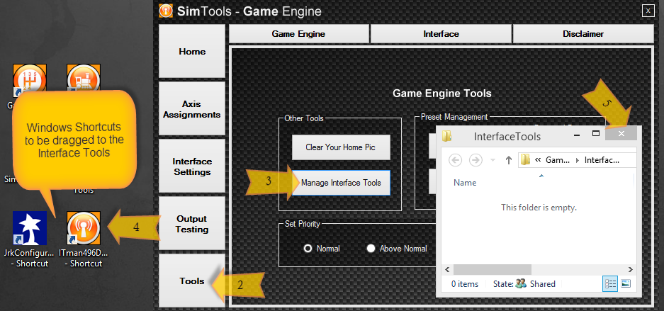
Manage Interface Tools
As the name states this allows us to set Windows Shortcuts that may help us to setup our interfaces and may include motor driver applications and specialized dash board application, or any other application that you want to run with your Simulator.
Please to make things easier send shortcuts to the desktop of the application you wish to include on the possible eight buttons then add them with the following steps to SimTools:
- Open the SimTools Game Engine.
- Press Tools on the right hand button bar.
- In the group Other Tools, Press Manage Interface Tools.
- Now just simply Drag the Windows Shortcuts to the directory that appeared from step 3 and Drop.
- Then Close the Directory.
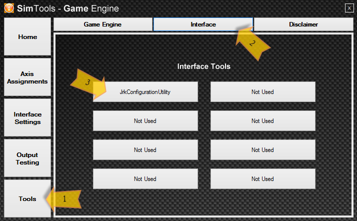
Now how do we use the previously installed Windows Shortcuts ?
The Shortcuts become buttons with in the SimTools Game Engine’s – Tools section.
Now these buttons will automatically update themselves and can be changed any time by simply redoing the steps above.
To gain access to these Buttons we:
- Press Tools in the right button bar.
- Press Interface in the top button bar.
- Now we can click the button that is now marked with the Shortcut’s name to start our application.
A nice easy way to access our extra stuff from within SimTools.